
COMPLETE GUIDE TO FLASHING THE THINKDIAG 2 ADAPTER TO ProDiag
ThinkDiag 2 is an advanced OBD adapter. For advanced firmware versions or recovering a “stuck” device, it must be physically flashed via a programmer (ST-LINK V2 or J-Link). This guide covers the entire process—from opening the housing, connecting the programmer, flashing the firmware, to verifying the device functionality.
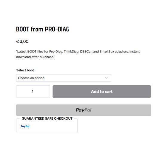
Note: Flashing files required for your device can be purchased here: ProDiag Boot Files
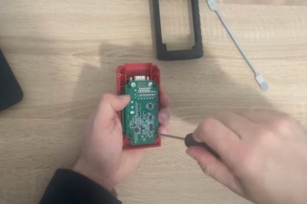
1. Opening the Housing
The ThinkDiag 2 housing is plastic, with clips holding the top and bottom together.
Steps:
- Remove any rubber protective cover if present.
- Use a thin plastic prying tool or a phone opening tool. Do not use pointed screwdrivers, as they can damage the plastic or internal components.
- Locate the clips in the middle of the housing. Start on the side opposite the OBD connector and carefully work around the housing until all clips are released.
- Once opened, the PCB with the microcontroller and programming test points will be visible.
2. Locating and Connecting Programmer Pins
On the ThinkDiag 2 PCB, there are pads or small connectors for connecting a programmer. Key pins are:
- GND – Ground
- 3.3V – Power supply
- SWDIO – Data line
- SWCLK – Clock line
Connect them directly to an ST-LINK V2 or J-Link programmer.
- If using a soldering iron, solder thin wires to the test points.
- Alternatively, small crocodile clips or pins can be used, but connections must remain stable.
Double-check pin layout to avoid short circuits or microcontroller damage.
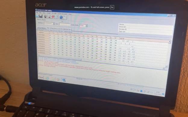
3. Flashing the Firmware
- Connect the programmer and plug ST-LINK V2 into your computer USB port. Launch STM32 ST-LINK Utility. The software should detect the ThinkDiag 2 microcontroller.
- Select “Program” or “Load File” and load the specific ThinkDiag 2 firmware (.bin file).
- Click “Start” and wait for the process to complete.
- Do not move wires, disconnect the computer, or remove the adapter during flashing.
- The process usually takes less than a minute.
- Once the software confirms a successful write, flashing is complete.
4. Reassembling and Verification
- Disconnect the programmer wires and carefully place the PCB back into the housing.
- Close the housing until all clips snap into place.
- Connect ThinkDiag 2 to the vehicle’s OBD port and launch the ProDiag app on your phone.
- Log in, enable Bluetooth, and connect the adapter. Default code is usually 1234 or 0000.
- Run a vehicle diagnostic to ensure proper functionality.
5. Troubleshooting
- If the programmer does not detect the microcontroller, check connections and power supply.
- If flashing stops mid-process, try again.
- If the adapter is unresponsive after flashing, the wrong firmware may have been used; reflash with the correct file.
- If Bluetooth fails to connect, remove the old pairing on your phone and reconnect.
Conclusion
The ThinkDiag 2 adapter is opened with a plastic prying tool, connected to ST-LINK V2 or J-Link via the SWD interface, firmware is uploaded through STM32 ST-LINK Utility, and then the adapter is reassembled and used with the ProDiag application. Proper flashing ensures maximum compatibility, stable operation, and access to all ProDiag features.